

| Home | Builds | Racers | Pilots | Crew | Contributors | Max | Racer Friends | Links | Credits |
| 1988-1989 Beginning | 1989-1990 Mock Ups & Test Beds | 1990-1992 First Streamliner |
| 1992-1994 Second Streamliner | 1994-1996 Third Streamliner | 1996-1997 Fourth Streamliner |
| 1997-1998 Fifth Streamliner | 1999-2000 Fifth Streamliner | 2000-2001 Fifth Streamliner |
| 2000-2001 Fifth Streamliner | 2000-2001 Fifth Streamliner | 2002-2003 Fifth Streamliner |
| 2003-2004 Sixth Streamliner | 2004-2005 Sixth Streamliner | 2005-2006 Seventh Streamliner |
| 2006-2007 Eighth Streamliner | 2007-2008 Eighth Streamliner | 2007-2008 Visit to Thunderdome |
2004-2005 Sixth Streamliner |
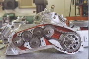 |
| Click the photo above to view a photo album |
|
The debut of streamliner number six during the Bonneville Speed Week trials produced only one run, which by any standard was an unsuccessful attempt on the record to be the "World's Fastest". After the streamliner's return home to Wichita, a thorough thought process took place, covering what went wrong, and what went right, in order to prepare for the next year's attempt. In order to reduce redundancy, this narrative will only highlight what was done, details will be found in the Build Diaries. The body was retained; however, I did take the wheel hump out of the nose, and built a new canopy hinge system. Most of the modifications during the 2004-2005 time span had to do with engine, drive line, clutch, ignition, and fuel tank. The fire bottles and CO2 bottle were relocated. These changes took the entire year, lots of machine work, and lots of fabrication. The streamliner was finished just prior to the Bub Meet, which I decided to attend instead of Speed Week. I didn't want to put up again with those 4 and 5 hour lines.
Build Diaries
Slider ClutchJust got back from Belle Plain, Kansas to pick up the slider clutch plates for the new slider lock-up type clutch which will be used in the new design. The ART drag clutch is based on a Kawasaki basket with larger root thickness special Barnett plates, which have much more friction area than the Kawasaki. Also, the clutch had two extra plates and a 1500 pound pressure plate. It was torque tested to 400 hp. I thought that this would be plenty of clutch for the liner. I was wrong on this one. The clutch just wasn't strong enough to hold the power. Everyone who first thinks about coupling two engines together, usually comes to a conclusion that if the cylinders were staggered 180 degrees on their firing, in essence you would have a 4 cylinder radial engine. This in theory would give firing impulses near equal degrees, not as good as a 4 cylinder inline engine, but close. Yes, the 4 cylinder engine's chain lives longer than say, a single or a twin's. The difference between a 4 cylinder inline engine, and 2 v-twin engines is that the 4 cylinders are attached to one crankshaft on the inline 4 and the v-twins have two separate crankshafts, as the fire impulse on a given cylinder of an inline 4 does not go through a chain before the final drive output. Unfortunately, this is what makes it so difficult to couple two engines together with a chain. If the firing strokes of 2 of the cylinders on a double v-twin power unit are not phased together, it just won't work. It will tear the chain in half immediately. If the engines are phased 180 degrees from each other when the cylinders fire, the piston accelerates, and loosens the chain, as the other cylinder is decelerating. When the other cylinder fires, the piston is accelerated, and this takes the slack out of the chain quite abruptly. This causes a tremendous amount of strain in a jerking action. It will literally pull the chain apart every time, no matter what kind of chain you put in there.
Clutch II believe the reason the mechanical device that disengages and engages the crankshaft rotation to a wheel, eventually transmitting the crankshaft rotation to the wheel, causing it to rotate, had to be called something that would reflect its mechanical function. Hence the word clutch is used. All clutches are devices that clutch together two objects, as on a motorcycle the crankshaft and the rear wheel, or would it be the clutching together of the clutch plates? As a torque converter which has no clutch plates performs the function of transmitting crankshaft rotation to wheel rotation, the later would be correct. Since the invention of the internal combustion engine man has saught to increase the efficiency of a given amount of swept volume. As the given amount of swept volume increased, clutches had to keep up with the increase of power. The problem that the racer has in most cases concerning clutches, is that he more often than not is working with a factory produced machine where the manufacturer designed the machine with a given horsepower and designed a clutch which would transmit that horsepower. I have found that in most cases the factories run into the same problem that the racer does, many times increasing the hp, leaving the clutch unattended, and eventually either overpowering the clutch, or eliminating any fudge factor the original design might have had. This ordeal has plagued Black Lightning from the start. In 1996 the liner went to the salt with a modified V-2 clutch, more plates and heavier springs. This clutch was grossly inadequate for the hp produced. Cost $1,200. In 1997, a total rethink on the clutch was in order. In 1997 my thoughts were not very flexible, so naturally my thinking was, "It's a motorcycle, a very powerful one, for sure, but nevertheless a motorcycle." So a motorcycle clutch it had to be. The most powerful motorcycles on the planet in 1997 were the blown fuel inline "4's" making their way across the other big pond from Japan, and with a little American ingenuity, managed huge horsepower readings in the neighborhood of 4 to 5 hundred. As there were literally hundreds of these bikes in the U.S. doing battle every weekend, I thought the clutch problems had to have been pretty well solved. The four factors involved which make it work are: First, friction coefficient between the plates, this has to do with the lining used on the clutch and the lining's ability to withstand heat. Second would be the combined area on the mating surfaces of all clutch plates. Third would be the amount of pressure applied to the mating surfaces. No problems so far, but number four had to be addressed, and that was clutch speed. As the inline 4's were turning around 12,000 rpm, and the gear ratio between the clutch and the crankshaft was around 1.5 to one, this meant that the clutch was turning around 8,000 rpm on the inline 4's. The clutch's location in most motorcycles is between the engine's crankshaft and the transmission. The torque developed is transmitted to the rear wheel through the transmission. When the streamliner is running at 6,500 rpm, the clutch will be turning a little over 4,000 rpm, as the ratio is 1.555 to one. A transmission is nothing more than a torque multiplier or reducer, transmitting a given amount of torque, depending upon the efficiency of the swept volume at a given rpm. The streamliner at 6,500 rpm develops 1 foot pound of torque each time it fires. That torque is transmitted to a clutch spinning at 4,000 rpm. The transmission in low gear transmits the torque to the rear wheel. In low gear the torque, or turning force, has a factor in proportion to the gear ratios in the transmission. In other words, the rear wheel is easier to turn due to the number of times the engine is firing in relation to the rpm of the rear wheel. The clutch speed is a constant with engine rpm, as they are mechanically married together. The engine and clutch speed is not a constant with a rear wheel when a transmission is employed in the drive train. When the transmission is shifted into a taller gear, the rear wheel receives fewer torque impulses from the engines firing, thereby making it harder on those torque impulses to do their thing. Hence, harder on everything between those impulses and the rear wheel, where lies a clutch which remains constant. If the clutch speed were to increase in proportion to rear wheel speed, the clutch would not be affected by additional torque loads. The torque load on the clutch would remain the same, so therefore the closer you can get the clutch speed to the engine rpm and the rear wheel speed, the better off you are. It takes less clutch, and she won't get as hot. So knowing that the clutch speed on the 4's was greater than the clutch speed I would be able to obtain, due to the physical make-up of the Vincent cavity where the new clutch would find a home, I found a company called A.R.T. and presented them with my problem of clutch speed. They took on the job to design a one off clutch that would do the job. After two months of waiting the clutch was finished and I exchanged $3,400 in greenbacks for the clutch. Of course it came with a spare set of clutch plates. I used the clutch at the Bonneville runs in 1997, where it held during it's only run, which ended in a crash. Stu Rodgers of the U.K. was the pilot that year, and in 1998 the clutch held while pulling a deployed parachute to 151 mph on it's third run. Don Angel from San Diego earned his 150 mph license on the run, but unfortunately the liner went on its side again. The clutch was used in 2001 during Vibrac's dyno test of my 1998 engines. The clutch held the 254 hp reading of the dyno, and the clutch held again in 2002 when Black Lightning, known at the time as the Vibrac streamliner, was under lease to the Canadians. In November of 2002 I began the job which took the next two years, redesigning and building a completely new streamliner in my shop in Wichita, Kansas. I contacted Terry Prince and asked if he would consider building stroker crankshafts for Black Lightning. He agreed. John MacDougall, a former member of the Vibrac team, wanted to help. John had rebuilt many Vincent engines, and I had heard only good things about his abilities. As he had Vincent tooling in his machine shop, I asked him to coordinate the building of the strokers and the cylinder muffs with Terry Prince and to procure cylinder liners from L.A. Sleeve. John worked approximately three months in Canada on the Black Lightning project, making the drive side main shafts for the strokers, assembling and balancing, and machining the cylinder muffs to accept the oversize liners. All the while I was working in Kansas, U.S.A. on the Muncie three speed transmission, blower drives, manifolds, remote starter, prepping and boring the cases to accept the larger sleeves, etc. After this was completed, I drove to Vancouver, Canada and John and I worked for about 25 days assembling the motors. The new streamliner made her debut at Speed Week, August 2004, reaching a clocked speed of 153 mph. At the 2 1/4 mile marker, the fastest 2 1/4 mile speed ever recorded among any of the past five Vincent streamliners. We were limited to 150 mph on the run by the scrutineers. The now 3000cc power plant developed major torque, which the clutch refused to accept for the first time.
Clutch IIAnother thing that affects a clutch's ability to do it's job, is the diameter of the clutch plates. The physics of a lever can best explain this. The longer the lever is from the fulcrum point, the more work will be accomplished with a given pressure. In the case of the clutch, a larger diameter clutch plate can transmit more torque than a smaller diameter with the same givens, in friction area, spring pressures and so on. What about my slipping clutch? A new clutch was in order. I needed a clutch that would meet the following criteria. It would have to be able to transmit 600 foot pounds of torque time and time again. This would give me a 100 pound of torque wiggle room. Next, the clutch had to be serviceable in the alotted turn around time during a record run. The two fastest record contenders at the moment are the E-Z Hook Streamliner, and the Ack Attack Streamliner. Both do not use a tow up; they drive off the line under their own power, so Black Lightning will do the same. Tow ups will be eliminated, as it's a safer way to go. The Vincent streamliner will go with the flow on this one. I knew the clutch would have to be designed to launch a 1900 pound missile pulling an overall gear ratio of 1.4 to one. Of course it will get underway in low gear, which will lighten the load so to speak. The clutch plates would have to be an off the shelf item, current in design, and readily available for spares. The parameters were set in stone. Now all I had to do was do it! The clutch project took a month and a half to complete. I've just finished building a three plate slider clutch that is attached to the HYVO chain drive gear, with 6 5/16" counter sunk cap screws. It has 3 1/2" hardened pins that take the blunt of the torque transfer from the engines to the jack shaft. A slider clutch is basically designed like any other plate type clutch, as far as the clutching together of clutch plates, transmitting the torque from the prime mover, i.e. the engines crankshaft rotation, to the jack shaft. The clutch plates consist of four 1/4" thick steel plates and measure 7 1/2" in diameter. There are six 3/4" concave radius' outboard of the clutch plate which serve as very robust dogs which marry the disks to the clutch basket. The three bonded clutch plates have an outside diameter of 6 1/4". The bonded area is from that dimension to the inboard circumference, which is 4". There are 4 heat expansion slots incorporated into each plate. The clutch plates have been broached to 1 1/2" with 16 tooth spline. Again quite a robust unit to marry itself to the 1 1/2" jack shaft. Both the steel plates and the bonded plates are made in Switzerland. The bonding material was developed by the European AirBus for their braking material for the plane. Very high tech and very expensive. One set of clutch plates cost $900 U.S. The characteristic of the bonding material is unique in that it's friction coefficient increases as the material gets hotter during it's sliding phase of operation. The heart of a slider clutch is it's pressure plate assembly and the mechanics of it's operation. The plate is so designed so as to accept a steel pressure plate that has 6 threaded studs that protrude through floater holes in the main portion of the assembly. That assembly is attached to the six adjustable 3/4" stands. Springs go over the six studs. The opposing pressure that the springs provide are adjustable by nut adjustment. There are six slots in the main plate which accept six fingers. The fingers are in a radial configuration and have a 1/4" hardened pin which lies in a milled trough in the main plate. Quarter inch holes are drilled in the outer portion of the fingers. These holes are mounting holes for weights which are nothing more than equal weight washers. At speed the clutch will be spinning at 4000 rpm. The floater pressure plate is moved to it's engaging position by the fingers. The fingers have a ratio of 5 to 1 at its fulcrum point. The fingers are nothing more than levers which depend on centrifugal force, providing movement of the finger lever. The opposing force on the pressure plate that the fingers are moving is the spring pressure. I needed more information as to how to initially set up Black Lightning's home built clutch. The only thing to do was to go to the people who have been there and done that. First I called my old drag racer buddy, Bonni Truett. Some of you may have heard of him, as hundreds, if not thousands of H.D.'s are using the "Truett and Osbourn" stroker crankshafts. Anyway, the only useful information I got out of Bonni was that the air gap of the clutch plates, when collapsed tight by hand should be .030 to .040. Seems kinda tight, but a couple of other racers have confirmed the gap since. Next I called the Ram Clutch people, who build these things at a cost of $3,800. A friend had told me that they had a lot of good data that I needed for my initial set up. I gave them the clutch plate, dimensions, finger geometry, number of fingers, finger swept circumference, clutch speed at idle, clutch speed at speed, preferred start lock up speed, and preferred lock up speed. It was in a matter of not more than 60 seconds that I had my answer for initial set up. Take 1/4" out of the free length of the springs. Add 50 grams of weight to each of the six fingers. They said this is what the clutch should do--the clutch will start to lock up at 1600 engine rpm, will totally lock up at 3,000 rpm, the clutch will have 2,900 pounds of pressure on the clutch plates at 6,500 engine rpm, and the clutch will transmit 850 foot pounds of torque. Perfect! Perfect! Perfect! The clutch is finished, and it looks like it's going to work. The salt attacks everything made of metal, so all of the steel parts of the clutch will be cad plated, and the aluminum parts will be anodised. As the clutch is now external, a moisture proof bag will be placed over it when laid up after the day's runs. The clutch weighs in at a whopping 28 lbs. This thing is a serious hunk that will be spinning at 4,000 rpm. Hence I've had it balanced. The clutch was balanced as a unit, except for the friction clutch plates. The three friction clutch plates were balanced separately.
TractionBlack Lightning's traction (the rear tire's ability to make contact with the salt) was improved quite a bit by gearing the two engines together. The old chain driven way of doing things pertaining to the coupling of the two Vincent engines was unsatisfactory. The front engine needed a minimum of 10 degrees lead on the rear engine. This was the only way that you could keep the chain from disintegrating, and parting ways. That is, the two front cylinders were firing at approximately the same time, as were the two rear cylinders of the two engines. As the chain stretched, the 10 degrees lead would grow 10,11,12,13, and so on, until I had to replace the chain, which put it back to the original lead of 10 degrees. Then the process would start all over again. Another thing that's important is power impulse duration, where the expanding gases (which is the ignited fuel in the cylinder) expand, forcing the piston down on the power stroke. The force which creates torque on the crankshaft is not a constant, due to the fuel's burning characteristic, which starts with a small flame, and grows at a faster rate during the burn cycle of the fuel. As the mechanics of a crankshaft are varying a great deal during the power stroke, meaning that during 180 degrees of crankshaft rotation, the leverage goes from zero at top, to it's max at 90 degrees, and back to zero at 180 degrees bottom. Therefore the power impulse duration has a definite fingerprint, and there is a definite spike in the torque to the rear wheel, as the two engines, with a chain coupling them together, and the front leading the rear by 10 or more degrees, increase the power impulse duration of the two engines by overlapping the two engines power impulse fingerprints. By gearing the engines together the 10 to 15 degree overlap of the two engines power pulses were eliminated. Both engines will be fired at the same time, hence decreasing the duration of the power pulse fingerprint. When the crankshaft turns over one time, the rear wheel does the same. As the engines are four stroke, and there are two cylinders firing at the same time with their fixed power impulse duration, the rear wheel should receive one power impulse per revolution shorter in duration. As the driving torque to the rear wheel occurs during the duration of the power impulse from the burning fuel, this is the only time the rear wheel feels inconsistent torque force. The duration of this inconsistent force is fixed in the volumetric efficiency of the mechanical pieces employed in the engines. After the torque force from the burning fuel takes place, the rear wheel then is receiving a kinetic force from all of the gear train's mass, as well as the crankshaft's mass. This kinetic force is not violent in nature, but rather smooth in it's deliverance to the salt through the wheel and tire. The tire has a friction coefficient which at speed will be a constant, other than the liner becoming lighter due to the fuel being burned at a high rate. When the power impulse occurs, the spike from that impulse causes the tire to break traction from the salt surface. The duration of this spike in torque determines how much the wheel is turning faster than the liner is actually going. The shorter the torque duration, the faster the wheel's speed is reduced, as once the wheel or tire breaks traction, the easier the tire accelerates. A longer power impulse duration really gets the tire spinning. All racers who have been there know that this is not hogwash, but a fact. If you were to take a dirt track sprint car, and put a V8 engine, with a given torque and horsepower, proven on a dyno, and take a four cylinder engine with the same torque and horsepower, proven on the dyno, the four cylinder would have better lap times than the V8 in the same car, due to less impulses providing better traction. Once you start the wheel spinning, the further you can get the power impulses apart, the better it is, and traction increases. This is a pretty good advantage that Black Lightning has over the multi-cylinder machines that are in the race to be the Worlds Fastest Motorcycle.
Engines II had been turning the blower much too tight, two to one to be exact, which produced a manifold pressure of around 43 pounds at 4500 engine rpm. If Don Angel hadn't turned the engines off when the throttle stuck, there would have been a serious melt down due to the nozzle size. They were calculated for 25 pounds boost at 6500 engine rpm, much too small for that kind of boost. I found several things wrong when I tore down the engines, all due to human error. So where did I mess up? First, the blower had far more boost then I figured it would. No dyno testing had been conducted on the complete redesign of the engine package, going from 2000cc to 3000cc, changing cams, ignition, you name it. Everything was improved and made better. Or so I thought. I'm changing the ignition system back to a redesigned electronic ignition. I've procured the necessary parts from DYNA Ignition at cost, and am in the process of building the necessary drive components. When I tore down the engines for the 2005 rebuild, I also discovered that number one piston had blown the rings and melted the thrust side of the piston, going past the rings, and holing the skirt below the oil ring. The other side of the skirt had only slight scoring and looked almost new. Number three piston had started to follow the lead of number one in the melt down, but didn't get to the point of number one. Number two piston and number four piston looked new. This was a bit perplexing, and required some thought as to what was going on. I found several things to be the reason for #1 and #3 giving up the ghost. First, there were three reasons for the lean condition. The nozzle sizes were too small for the extreme blower pressure. The blower is a positive displacement type, and #1 and #3 cylinders get more air than #2 and #4 due to the 50 degree differential between the filling of chambers stage. Last, the home built nozzles in the hat were made from aluminum, which the fuel had corroded, causing #1 and #3 to partially plug up. That caused the leaning of #1 and #3 cylinders. This will be corrected by increasing 1 and 3 port nozzle size over 2 and 4. The oversize will be determined during dyno testing. The four hat nozzles have been replaced with custom built nozzles by Ron's Racing, which employ changeable jets and aeration holes for atomization. ost $200--they will not corrode and plug up. Why did only the thrust side of the pistons on 1 and 3 receive damage, and not the non thrust sides? If it were an inadequate clearance, and the pistons grew, due to the lean condition, both piston skirt sides would have been scored and you would have observed "Black Death", as it is referred to when this occurs. It had to be a lubrication problem. Further investigation revealed that when the hole in the liner was moved downward one half inch to put the oiling hole just below the oil ring where it belongs, the hole fell below the crankcase bore. The liner had been grooved to provide an oil passage to the hole. As there was no crankcase material surrounding the ground passage and hole, the oil to lubricate the pistons thrust was merrily being dumped into the crankcase. Not a good thing. This was taking place on one and three. Two and four were receiving partial lubrication as the crankcase material dropped off at the bottom of the holes. John had gone to a lot of trouble to make sure when he machined the Terry Prince special one half inch longer muffs, and installed the 90 mm bore Los Angeles sleeves, that it was done right, and they were done right. He even went to the extent of boring out a set of HRD cases and fitting them up to determine the oiling holes, notching the liners for rod clearance, which is required due to the one inch increase in the stroke. I was working on the engine cases here in Wichita, and had bored them to accept the larger sleeves. Where I goofed was when I took the engines to Vancouver for assembly. "Murphy's Law" showed up in the shop the day we assembled the top end. We totally overlooked the problem. My cases had less meat in the casting than the mock up HRD cases. Human error happens to all who "walk the walk", and that's a fact. So what about the piston redesign change? The pistons, which are at this moment being manufactured by Aries, have the following specs: They will be the same size as the 2004 pistons, bore, wrist pin size, and compression height. The changes are a Dykes stainless steel top ring, instead of the chrome ring. The second ring will be a gapless ring, a two piece unit, (two thin rings installed 180o degrees apart in the ring groove), eliminating the gap. This type of ring is used extensively in blown fuel engines, which helps a great deal in the prevention of the washing of the oil from the cylinder walls, which large quantities of fuel injected into the cylinder have a propensity to do. This also helps in the fuel contamination of the oil, always a problem with blown fuel motors. The pistons will be hard anodized, which help prevent galding and also prevents fuel corrosion. Eight buttons will be installed in the skirt, four on the thrust side and four on the opposite side. When I receive the pistons I'll have to turn the pistons in the lathe, machining the buttons to a zero clearance slide fit in each cylinder. The buttons are made from a graphite Teflon material. The wrist pin will be held in place with aluminium buttons, eliminating the spiral lock circlips. Cost of the pistons, around $800. The new blower drive is about 80% complete. I used an enclosed number 520 chain, running in oil in 2004. This was all eliminated for 2005 in favor of a 1 1/2 inch wide 8 mm pitch tooth belt. The pulleys, belts, number of teeth, and the fixed distance between the rear engine crankshaft and the blower drive had to be calculated. The blower pulley is 38 tooth with a pitch diameter of 3.810 inches. The crankshaft pulley has 53 teeth with a pitch diameter of 5.314 inches. This will give me a speed ratio of 1.395 to one. I used the only known means to calculate what I needed to achieve 25 pounds boost at 6500 engine rpm, and that was running the blower two to one, it had 43 pounds boost at 4500 engine rpm. Cost to make this change is $350 and a weeks work doing the necessary machining on the pulleys. The blower shaft, which connects the blower pulley to the blower timing gears, has been replaced with a larger shaft size unit made from heat treated 4340. The four bolt pattern, which failed in 2004, has been upgraded to an 8 bolt pattern. The belt is a Gates poly chain G.T.2 made with Kevlar strands, stronger than the old steel type strands. The blower was boxed up today, and will be sent to California to The Blower Shop Monday to be professionally overhauled. It's best to leave this job to the guys that know how to set one up for racing and make it live. The cost will range from $400 to $1100, depending on how badly it was hurt in 2002 and 2004. I've totally rebuilt the transmission for 2005. $700 worth of gears and $250 worth of E.D.M. work to complete the job. The gears in the later Muncie transmissions were back cut to prevent them from popping out of gear. The old style gears were in the box in 2004, which was the reason for the problems encountered.
Engines IIA few words on the visual inspection of a spark. First, color of the spark determines how much heat in BTU's is being developed. This can best be demonstrated by firing up the cutting torch; first a yellow flame, and as more oxygen is applied to the available fuel, the flame turns blue, and adding even more oxygen, turns the flame to a white blue color. This proves that the ignition spark is at it's hottest, and contains more heat, when a whitish blue spark is obtained. The size of the spark is in proportion to how much volume of heat is available to ignite the fuel. A coil's purpose is to change low voltage into high voltage. A unit could be constructed to achieve 35,000 volts, say, without the use of the physics of a coil; however, it would take a battery that would contain 17,500 cells and wire the size of your arm to take the E.M.F. The unit would be about the size of a house, and would weigh tons, hence, the coil seems to be the better way to go. What are the components that are required to make a coil? They are a metallic core, a few turns of insulated heavy gauge, usually copper, wire around the core, which is called the primary winding, and many turns of insulated copper wire, small gauge, wound inside the primary windings. This is called the secondary windings. How the coil components work: The low voltage, or primary circuit, has a flow of current going through it when the points are closed, or in an electronic ignition system, a circuit is completed and the ignition switch is on. The primary winding is saturated to a varying degree by the OHM resistance of the primary circuit, the dwell, or time the primary circuit has current flowing through it, and how many times the circuit is being completed, i.e., at an idle of 1000 rpm the circuit is completed 500 times a minute, on a four stroke engine. Therefore the circuit is completed more times at higher engine rpm. So what's going on here, is first a saturated primary coil, that varies at different rpm, due to the fact that a fixed circuit with the size of the primary wire being the factor, bumped against the time factor current is flowing through it. This changes the amount of heat in the wire itself; as the wire heats up it's resistance increases. At higher rpm the primary circuit is cooled, due to the real time that current is flowing through the circuit. When the primary circuit is complete, it produces a magnetic field around the secondary windings, but when the circuit is broken, the magnetic field collapses. A magnetic field of flux crosses the secondary windings. The voltage in the secondary would melt the secondary windings, if there were any appreciable dwell of the magnetic field of flux crossing the secondary windings. The secondary windings magnetic field collapses and the high voltage, around 35,000 volts, has to go somewhere, hence that spark you're observing is the voltage crossing an air gap of the spark plug electrode going to ground. Coils are produced by virtually all industrialized nations for their purpose. This does not mean they're equal in performance. First and foremost is the material that they're made of. The best copper wire comes from Chile. The best wire insulation is made by Westinghouse, and the best encapsulating material comes from DuPont. This, coupled with the fact that there are more performance engines built on a daily basis in the USA than all of the rest of the world combined, keeps such things as performance coils in the forefront, where research development is so necessary for a company such as Dynatech to be competitive in a never ending battle for market share. The racer mentally has to be satisfied. Whatever works best, sells best. In about two weeks I'll be putting together the components of Black Lightning's ignition system. The most important thing to do is to establish the OHM resistance of the coil. I'll have to consider several things in order to come up with the right choice. For instance, where does the benefit of primary coil saturation end? This is where the current being pushed through the primary coil, which is controllable, becomes so great that the coil winding heats up the coil to destruction. If the points by happenstance are in the closed position, and the current from a fully charged battery is flowing freely through the primary coil, and isn't being circumvented from time to time to give it a cooling down period, the primary winding heats up due to the inherent resistance that all coils have. The heat from the winding, by convection, finds it's way to the secondary windings, which are unsuited to take the heat abuse, due to it's small wire size. The only relief the coil is getting from the melt down, was the convected heat finding it's way to the surface of the encapsulation cocoon and by radiation, transfers heat to the ambient temperature of the atmosphere. Heat traveling from hot to cold. So knowing what can happen when coils are overheated, it's wise to keep the coil cool enough so melt down doesn't occur, yet saturate the primary winding, so when the highly saturated winding is collapsed the optimum magnetic field of flux is created, which in turn creates the optimum saturation of the secondary winding, and when collapsed gives me that 45 to 50,000 volt blue white spark. When building your ignition system, it is paramount that you keep all of the above basics in mind. To put it simply, it isn't rocket science, it's nothing more than a juggling act, getting the lowest OHM resistant coil in your circuit that will live. Using a coil of quality that can stand some current on the primary, liquid cooled coils are good, cooling fins on the encapsulating cocoon of the windings are good. One other thing. That old wive's tale that a higher compression engine needs more spark to jump the air gap of the plug is utterly nonsense. May your spark be a whitish blue--you'll need that to get the checkered flag.
IgnitionJust finished the ignition system for Black Lightning's 2005 LSR attempt. The final selection on the dual coils are 2.89 OHM by Dyna. The blower drive is now 90% complete. I finished up the idler adjustment pulley today. Tomorrow I'll start work on the adjustment plate and pivot for the pulley. After I finish with that the blower drive will be ready to transmit some power. Got an e-mail from Aires Pistons. There's no Dykes ring available for my bore size, so I'll have to have them made. Evidently Aires doesn't make their own rings, but the fellow I'm in contact with says his ring manufacturer can make them. Hope it's not too long a wait to get them made. Being as how I can't get them off the shelf, I'll have eight of them made.
ChancesWhat are Black Lightning's chances? Here are some statistics the way I perceive them. There are four motorcycle streamliners capable of coming out on top. They are: EZ Hook, Ack Attack, Bub Lucky 7, and Black Lightning.
SPEEDS TO DATE
FRONTAL AREA
HORSEPOWER
TRACTION
CREW EXPERIENCE
RIDER EXPERIENCE
TOTAL RUNS MADE
FINANCIAL BACKING
AERODYNAMICS
WEIGHT ADVANTAGE
AVAILABLE WORK FORCE
DEDICATION When you write it all down, Black Lightning is definitely in the running to be the World's Fastest.
BrakesBoth Don and Hartmut have said a better brake would be helpful. A bit of research was in order, so I talked with the premier brake manufacture of race cars in the U.S., i.e., Wilwood, who recommended the following set up for my application. As weight was not a problem, a 10 1/2" diameter cast iron rotor 3/4" wide with cooling fins between the rotor friction faces was advised. The weight of the vehicle, the speeds that the mass had to be stopped, and the diameter of the rear tire in size, were all considered for the optimum brake set up. The brake lining is referred to as the "E" lining compound, which is for extreme high speeds and high heat. The caliper is a racing aluminium body with four pistons, the type used on high speed drag cars and NASCAR racers. A quick trip to the surplus yard and $50 worth of 7075 T-6 aluminium, and the last four days of labor making the bracketry for installation, has produced a brake that should work well. To make everything compatible, a Wilwood master cylinder was also procured and installed. The last piece in the gear train is finally finished and installed. What I'm talking about is the 23 tooth HYVO gear which is used on the input shaft of the Muncie transmission. Last year, the gear had a machined hole in the center, a new clutch was bought, and the center spline was removed and turned to size and pressed into the HYVO gear, and then welded on both ends. This was always suspect in my eyes. I never thought it was the way to do it properly, but I did it anyway. For 2005, a new HYVO gear was bought, and the 1 1/4" diameter 22 degree involuted serrated spline was EDM'd. The gear was re-heat-treated, as the teeth of the HYVO were the only thing treated when purchased. The center of the gear was quite soft. The new gear spline area has a full 5/8" width increase. The gear is much stronger, and virtually bulletproof. I spent, this last two weeks, over $1000 on all of this.
WindscreenI've been working on the canopy for the last five days. Much of the distortion of the polycarbonate window has been eliminated with the new windscreen. Not totally, but it's much better than it was before. The canopy itself has been made more user friendly. If you recall, the hinge of the canopy for 2004 was 1" wide with a 1/2" roll pin pivot, which was attached to the frame. Two pressure gas piston shocks were used on either side of the canopy, so that when the latch was released, the piston shocks would telescope and lift the canopy. The design seemed sound, but turned out to be no good in actual fact. We had a lot of trouble with the canopy. A lot of time was spent trying to make it work, but to no avail. The center 1" pivot pin hinge was not adequate to hold the five foot long, relatively heavy, probably about 15 pound canopy in position. It just flopped all over the place, and the hinge kept getting looser and looser. One other thing. The gas lifting shocks were mounted to the frame, and then to the canopy. This forced the canopy, in the closed position, compressing the lever actuating hinge to where you could not open the canopy due to the decrease in clearance of the latch. One other thing that caused the system to not work well was the fact that all of the fitting was done in my air conditioned garage, and on the salt the fiberglass shell grew in every direction, which didn't help the situation. For 2005, the hinge has been replaced with two outboard hinges, measuring 13 1/2" apart. They look much like the trunk hinge on a 1939 Buick. Anyway, this pretty much eliminates the athwartship movement of the canopy when raised. The hinge, being affixed to the fiberglass body, and then to the canopy, in lieu of the frame, seems to have helped a bunch. The canopy now returns to the closed position the same every time. The gas lifting shocks were removed to take the pressure off the latch. The same latch is employed this year as last. There are two notched slider bars on either side of the canopy. When the canopy is raised, gravity pulls the slider bars down, which engage on a pin and hold the canopy in position. The whole thing works quite well, and will be a definite improvement over last year. I think Don and Hartmut will like the new canopy operation much better, as it's easier to get into the liner. The canopy lifts much higher for more room, and the visibility has been improved a great deal. P.S. I had been struggling all day trying to get the slider bars to work like I wanted them to, as I've never taken any geometry classes, this was all done by, "well, let's see. This hole here needs to be over there." While all of this was going on, the canopy was being held up with my shop broom. Patti walked in to the garage while I was mumbling to myself how to solve the geometry problem. She took in the situation and asked simply, "Why don't you just use the broom?".
O Happy DayGot up this morning at 4:00 and started setting up a streamliner stop in front of the garage door. It was dark, but with the aid of a flashlight I had it all done by daybreak. Then the hard part came. I had to wait a couple of hours, as I felt firing the liner at 6:00 o'clock in the morning would have been detrimental to my health as there are a couple of testy neighbors on the block. So I waited anxiously to give that home built slider clutch a work out to see if the thing worked. O HAPPY DAY! It works great. Specs to ponder. The garage floor is concrete. The rear tire is a 600/15 Bonneville tire. The footprint is fairly large as there is 1000 pounds of weight on the rear tire. The overall gear is 1.39 to 1. At 6500 engine rpm, the liner will reach a speed of 225 mph in low gear. I put the transmission into low gear, started the engines, and with a very brief warm up time brought the engines up slowly to find out when the tire would break loose. I hit it right on the nose as far as the finger weights on the clutch are concerned. The tire started churning at 2500 rpm. This was done four times on the same start up. As the engines are alcohol motors, the last two run ups with a little heat in the cylinders produced awesome horsepower. The pilots will definitely have to be light on the throttle for the first hundred miles per hour, as you could virtually break the tire loose at will. My confidence that this will be the year certainly was enhanced by this test.
DoneAfter nine months of going out in the garage before dawn to put in anywhere from 8-12 hours a day, 7 days a week, I believe I can say that the Vincent streamliner is ready to take a trip between those two black lines at Bonneville. I've done everything I know how to do to make Black Lightning 2005 far better then any of my previous streamliners. The others were inferior in many ways, due to my lack of experience, funds and time. It's been quite a learning experience to finding out what works and what doesn't work. A streamliner is a unique machine, each of them differ in size, power plant and systems. There are many hidden things that have to be considered and engineered which aren't readily seen by the naked eye, but are extremely vital to the performance of the liner. The building of streamliner number six in 2003-2004, (as did the building of all of the other machines) gave me a good base from which to work for 2005. Increasing the crankshaft stroke from 3 1/2 to 4 1/2, and increasing the drive side main shaft size from 1" to 1 1/2" made a big improvement over the stock crankshafts which had been employed in streamliners number one through five. The crankshafts were made by Terry Prince and John McDougall in 2003. This year I built a robust slider clutch, and geared the two engines together. I also built a new ignition system, and redesigned the oiling system and pistons. All of the above systems work flawlessly. The Vincent streamliner is ready to seriously challenge the record for the first time.
Spark PlugsLast week, I called the Champion Sparkplug Racing Division hotline. I wanted to get their take on what plug to use for the record attempt. The fellow was quite interested in the Black Lightning Project, and was very helpful. I gave him the specs, around 7 to 1 static compression, 4 cylinder, 180 cubic inch, 25 pounds of boost at 6500 rpm, alcohol engines. First, the effective compression ratio was established at 6500 rpm. It will be between 15 and 16 to 1. The differential will be the barometric pressure of the day for Bonneville. The figures that I gave him, compiled, put the Vincent streamliner off the charts. He suggested three Champion Racing Sparkplugs, heat ranges are C57's, C55's, and C53's. The C57 equates to approximately in heat range value to a number 10 NGK. The C55 is colder yet, and the C53 has to be made at the North Pole, or possibly the South Pole, 'cause this puppy is cold--cold--cold! The electrode is platinum, and of the small wire type. Champion sponsored two boxes of each heat range. Amount of sponsorship would be around $180. It ain't over 'till the fat lady sings, and the fat lady is about to sing.
ResultsTen runs were made. Four by Hartmut. six by Don. All runs made it through the timed mile with no aborted runs. Timing slips as follows:
Run #1 Hartmut: 116.725 mph All runs but four entered the timed mile at 220 to 230 in accordence with Don and Hartmut's tachometer readings. I instructed the pilots to take the initial runs to 6000 rpm. On one of Hartmut's runs, while he was taking it to 6000 rpm, he had to back off to half throttle and entered the traps tachometer steady at 6000 rpm. Speed 220 to 230. The chutes predeployed through the traps on five of the runs. All runs actually decreased in speed from the entering trap speed to the end of the timed mile due to one reason or another. Kudos are in order for Black Lightning's two pilots, and to the crew for their excellent work, which made it possible to make 10 unoborted runs. All of this was done on a "fair" course, not a "good" course, and it was done on a 5 mile course, which is referred to as a short course, not a 10 or 11 mile long course. There was lots of water at the end of the 5 mile, unfavorable wind conditions. The liner was untested other than in my garage. Also, I had it geared for 385 mph. Much too tall for a short course. Of the ten trophies and prize money awarded at the 2005 Bub Meet, two were captured by Vincents. Steve Hamel, with his superbly prepared, unfaired, Vincent, took the award for the fastest metric V-twin at a speed of 151.688 mph. Black Lightning took the award for the fastest pre-1970 antique motorcycle, at a speed of 212.860. |